Part 2 of 6 in the Drone Mapping Checklist Series — one article per phase of a commercial drone survey, publishing every Friday.
The $4,000 Refly
An operator flew a 60-acre construction grading project at 400 feet AGL because “higher is faster — fewer flight lines.” The project spec called for 1 cm/px GSD. At 400 feet with the Mavic 3 Enterprise’s 4/3 CMOS sensor, actual GSD was approximately 3.5 cm/px — 3.5 times worse than the spec. The ortho looked fine on screen. Zoomed out, everything appeared sharp. But the civil engineer pulled the 1-foot contours and saw stairstepping artifacts across the entire graded pad. The point cloud density was too low to resolve the grade breaks. Deliverable rejected.
The refly happened at 120 feet AGL — the correct altitude for 1 cm/px GSD on that sensor. Cost: a full remobilization at $800-1,200 for travel, crew, and equipment. A lost schedule day. And the client conversation about why “centimeter accuracy” didn’t mean what the operator thought it meant. That conversation is the expensive part. You can absorb the mobilization cost. You can’t absorb the reputation damage of delivering data that doesn’t meet a spec you agreed to.
Second scenario. Same project type, correct altitude this time, but overlap set to 60/50 — 60% frontal, 50% lateral — over a freshly graded pad site. Low-texture terrain. Bare dirt with minimal features. No curbs, no painted lines, no vegetation edges for the algorithm to grab onto. Processing fails on 40% of the images. The feature matching algorithm can’t find enough tie points on homogeneous surfaces without higher overlap. The images are sharp. The altitude is right. But the software can’t stitch them because there’s nothing distinctive to match between frames.
At 60% frontal overlap on low-texture terrain, feature matching fails on a significant fraction of images and horizontal accuracy degrades noticeably. Raising to 80% frontal overlap restores reliable alignment and tightens horizontal RMSE into the sub-centimeter-to-few-centimeter range — a step change from 20 percentage points of additional overlap. The fix: refly at 80/75 overlap. Another mobilization. Another schedule hit.
Both errors are drone mapping mission planning errors — wrong parameters set before the drone ever left the ground. Not equipment failures. Not weather problems. Not software bugs. Parameter decisions. A mission planning checklist would have caught both: GSD calculation cross-referenced against the project spec, overlap selection matched to terrain type. Five minutes of planning math would have prevented $4,000 in rework.
Define the Accuracy Requirement First
This is the step most operators get backwards. They open the flight app, pick an altitude that seems reasonable, set overlap to the app’s default, and fly. Then they process the data and check whether the results meet the spec. That’s backwards. The accuracy requirement drives every parameter downstream.
| Project Type | Typical Accuracy Class | GSD Requirement | Contour Interval |
|---|---|---|---|
| Topographic survey (engineering grade) | ±2-5 cm horizontal, ±3-5 cm vertical | 1-2 cm/px | 0.5-1 foot |
| Construction progress/grading | ±5-10 cm | 2-3 cm/px | 1-2 foot |
| Stockpile volumetrics | ±5-15 cm | 2-5 cm/px | N/A (volume, not contour) |
| Agriculture/vegetation | ±10-30 cm | 3-5 cm/px | N/A |
| Real estate/marketing ortho | Visual quality only | 3-5 cm/px | N/A |
| Corridor mapping (pipeline, road) | ±5-10 cm | 2-3 cm/px | 1 foot |
For a deeper treatment of accuracy classes and how GCPs and positioning methods affect these numbers, see RTK vs PPK for Drone Mapping and the Complete Drone Mapping Workflow Guide.
Here’s the chain: the accuracy class determines the GSD requirement. The GSD requirement determines the flight altitude. The flight altitude determines the flight time and battery count. Every parameter traces back to accuracy. Start here. Not with altitude. Not with “what altitude did I fly last time.” Not with whatever the flight app defaults to.
If you don’t have a written accuracy requirement from the client, ask for one. If the client says “just make it accurate,” translate that into a specific class before you plan the mission. “Accurate” means different things to a landscape architect (±30 cm is fine) and a civil engineer (±3 cm or the data is useless). Get the number. Write it down. Every flight parameter follows from it.
GSD and Flight Altitude
Ground Sample Distance is the physical size of one pixel on the ground. It’s the single most important number in drone survey flight planning because it determines what the data can resolve. If a feature is smaller than your GSD, it doesn’t exist in your dataset.
The formula:
GSD (cm/px) = (Flight Altitude x Sensor Width) / (Focal Length x Image Width in Pixels)
That’s the math. Here’s the practical table — GSD by altitude for platforms you’re actually flying:
| Platform | Sensor | Flight Altitude (ft AGL) | GSD (cm/px) |
|---|---|---|---|
| DJI M350 RTK + P1 (35mm) | Full frame 45MP | 120 ft | ~0.9 |
| DJI M350 RTK + P1 (35mm) | Full frame 45MP | 200 ft | ~1.5 |
| DJI M350 RTK + P1 (35mm) | Full frame 45MP | 400 ft | ~3.0 |
| DJI Mavic 3 Enterprise | 4/3 CMOS 20MP | 120 ft | ~1.2 |
| DJI Mavic 3 Enterprise | 4/3 CMOS 20MP | 200 ft | ~2.0 |
| DJI Mavic 3 Enterprise | 4/3 CMOS 20MP | 400 ft | ~3.5 |
| DJI Mini 4 Pro | 1/1.3” 48MP | 120 ft | ~1.3 |
| DJI Mini 4 Pro | 1/1.3” 48MP | 200 ft | ~2.2 |
| DJI Mini 4 Pro | 1/1.3” 48MP | 400 ft | ~4.3 |
| Phantom 4 RTK | 1” CMOS 20MP | 120 ft | ~1.4 |
| Phantom 4 RTK | 1” CMOS 20MP | 200 ft | ~2.3 |
These are approximate values. Sensor spec sheets, actual focal length, and image dimensions vary between firmware versions and shooting modes. Calculate for your specific platform using the formula above. Don’t assume the table is exact for your configuration.
The decision rule is straightforward: pick the altitude that produces the GSD matching your accuracy requirement. Not higher “for efficiency.” Not lower “for extra detail.” The altitude matches the spec.
Flying higher than needed doesn’t just reduce resolution — it reduces point cloud density, which degrades contour accuracy and surface model fidelity even when the ortho looks acceptable. Flying lower than needed wastes battery and flight time. You cover less area per flight, need more batteries, spend more time on site, and produce more images that take longer to process — all for detail the project doesn’t require and the client isn’t paying for.
Match the altitude to the spec. That’s the job.
Overlap Settings by Terrain Type
This is the drone flight parameter most operators get wrong on low-texture terrain. The default overlap in most flight apps — typically 75/65 or 80/60 — works fine over structured environments with buildings, roads, and vegetation edges. It fails on bare dirt, gravel pads, fresh concrete, snow, and any surface where one square meter looks identical to the next.
The feature matching algorithm needs distinctive visual features to tie images together. On a textured surface — a parking lot with painted lines, a rooftop with HVAC equipment, a hillside with varied vegetation — there are thousands of tie points per image pair. On a freshly graded dirt pad, there might be dozens. Higher overlap means more image pairs covering each point on the ground, which gives the algorithm more opportunities to find and verify the sparse features that do exist.
| Terrain Type | Recommended Frontal Overlap | Recommended Lateral Overlap | Why |
|---|---|---|---|
| Structured (buildings, infrastructure) | 75% | 65% | Abundant features for tie point matching |
| Mixed (suburban, vegetated with clearings) | 80% | 70% | Variable texture requires higher redundancy |
| Low-texture (bare earth, gravel, snow, water edges) | 85% | 75% | Minimal features — algorithm needs maximum image pairs for matching |
| Steep terrain (>30% slope) | 85% | 80% | Effective overlap decreases on slopes due to perspective distortion |
| Corridor (linear infrastructure) | 80% | 70% | Narrow survey area — lateral overlap prevents edge dropoff |
The research backs this up. Published overlap-sensitivity studies consistently show that feature-poor surfaces — bare earth, snow, water edges — need 80-85% frontal overlap to maintain reliable alignment. At 60-70% overlap on those surfaces, processing failures become common and horizontal accuracy degrades rapidly. That’s not a marginal improvement. That’s the difference between survey-grade data and data a civil engineer rejects.
When in doubt, increase overlap. The cost is more images and slightly longer flight times — maybe 10-15% more time on a typical mission. The cost of insufficient overlap is a refly. A complete remobilization. The math is not close.
One more point on overlap: the numbers above assume flat terrain. On slopes, effective overlap decreases because the perspective geometry changes. A flight planned at 80% frontal overlap over a hillside with 30% grade delivers roughly 65-70% effective overlap at the steepest sections. If you’re flying over terrain with significant relief, add 5-10% to both overlap values. Or use terrain-following mode if your platform and flight app support it.

Battery Budget and Flight Line Planning
Manufacturer endurance specs are marketing numbers. They’re measured at sea level, no wind, no payload, constant altitude, warm batteries, flying until the aircraft initiates forced landing. You will never achieve those numbers on a mapping mission. Here’s what you’ll actually get:
| Platform | Manufacturer Stated Endurance | Realistic Mapping Endurance | Coverage per Battery (at 200ft, 80/70 overlap) |
|---|---|---|---|
| DJI M350 RTK (TB65) | 55 min | 38-42 min | ~30-40 acres |
| DJI Mavic 3 Enterprise | 45 min | 30-35 min | ~20-25 acres |
| DJI Mini 4 Pro | 34 min | 22-26 min | ~8-12 acres |
| Phantom 4 RTK | 30 min | 22-25 min | ~15-20 acres |
Coverage varies with altitude and overlap. Higher altitude and lower overlap cover more area per battery. Lower altitude and higher overlap cover less. The numbers above assume 200 feet AGL with 80/70 overlap — a common configuration for construction and topographic work. Adjust for your parameters.
-
Land at 25%, not 15%. LiPo battery voltage drops non-linearly. The discharge curve flattens through the middle of the capacity range and then falls off steeply. The last 15% is where low-voltage warnings and forced landings happen. Plan to land at 25% remaining — 20% absolute minimum. The extra five minutes you gain by pushing to 15% is not worth the risk of a forced landing at 250 feet over a job site.
-
Account for wind. Headwinds increase power consumption by forcing the motors to work harder to maintain ground speed. A sustained 15 mph headwind reduces effective endurance by 15-25%, depending on platform and flight direction. On a four-battery mission, that headwind costs you the equivalent of one full battery. Check the forecast. Adjust the plan.
-
Multi-battery missions. Plan flight lines so battery swaps happen at the end of a flight line, not mid-line. Most flight apps support mission resume — the aircraft picks up where it left off after a battery swap. Overlap the swap region by at least two flight lines to ensure continuous coverage with no gaps. A gap in coverage at a battery swap point is a processing failure that requires a partial refly — the most annoying kind of refly because you’re going back for ten minutes of flying and a full mobilization.
-
Buffer. For mission bids and project planning, budget one spare battery beyond what the acreage calculation requires. Equipment fails. Conditions change. A battery that tested fine at the office shows a cell imbalance on site. Wind picks up and reduces endurance on the last two flights. The spare battery is the difference between completing the mission and scheduling a return trip. On a 100-acre site with the M350 RTK at 200 feet — roughly three batteries of coverage — bring four. Always.

Flight App Configuration
The mission plan on paper means nothing if the flight app settings don’t match. This is where drone survey flight planning becomes execution. Every parameter you calculated in the previous sections has to be entered correctly in the app. Defaults will betray you.
-
Verify altitude matches GSD calculation. Don’t trust the default. Don’t trust what it was set to on the last mission. Enter the planned altitude manually and confirm it on the planning screen before you arm the aircraft. A 50-foot altitude difference between what you planned and what the app executes changes your GSD by 25-40%, depending on platform.
-
Verify overlap matches terrain type. Flight apps default to 75/65 or 80/60. If your terrain is low-texture and needs 85/75, set it manually. The app won’t look at your survey area and make that judgment for you. It doesn’t know you’re flying over a gravel pad. You do.
-
Verify camera settings. Shutter speed: auto is usually fine for mapping in good light. If you’re flying at speed in low light or early morning, set a minimum shutter speed of 1/1000s to prevent motion blur. At 200 feet AGL and 20 mph ground speed, a 1/500s shutter produces approximately 1 cm of motion blur — enough to degrade feature matching on detailed surfaces. ISO: auto with a ceiling of 400-800. Higher ISO introduces noise that the feature matching algorithm interprets as texture, creating false tie points. White balance: fixed, not auto. Auto white balance shifts between images based on scene content — slightly warmer over dirt, slightly cooler over concrete. Those shifts create color banding in the orthomosaic that looks unprofessional and can mask real surface color differences that matter for some deliverables.
-
Verify waypoint altitude reference. This is the GSD altitude overlap setting that catches experienced operators off guard. Is the altitude above takeoff point (relative) or above sea level (MSL/absolute)? On flat sites, it doesn’t matter — relative and absolute produce the same AGL. On sites with significant relief, they diverge fast.
A mission planned at 200 feet relative to the takeoff point means the drone maintains 200 feet above the launch pad — but if the terrain rises 80 feet from the launch point to the far end of the site, the actual AGL at the far end is 120 feet. That changes your GSD from 2.0 cm/px to 1.2 cm/px on the Mavic 3 Enterprise — inconsistent resolution across the dataset. Worse, if the terrain drops 100 feet from the launch point, the far end is at 300 feet AGL — GSD jumps to 3.0 cm/px and may not meet your spec.
Terrain-following mode fixes this on platforms and apps that support it (DJI Pilot 2 on the M350 RTK, DJI FlightHub 2, Litchi on some platforms). The aircraft adjusts altitude along each flight line to maintain a constant AGL based on terrain elevation data. If your platform doesn’t support terrain-following, plan separate flight segments at different altitudes for areas with significant elevation change.
-
Flight line direction. Plan flight lines perpendicular to the longest axis of the survey area for efficiency — fewer turns, more straight-line flying per battery. On sloped terrain, fly cross-slope when possible. Uphill/downhill lines create variable GSD as the terrain-to-drone distance changes along the flight line. Cross-slope lines maintain a more consistent AGL across each individual pass.
-
Crosshatch pattern. For projects requiring 3D models or dense point clouds — stockpile volumetrics, building inspections, terrain with steep cuts — plan a crosshatch pattern: two flight sets at perpendicular angles. This doubles the image count and flight time but provides the multi-angle coverage that dense reconstruction algorithms need. For flat ortho-only projects, single-direction flight lines are sufficient.
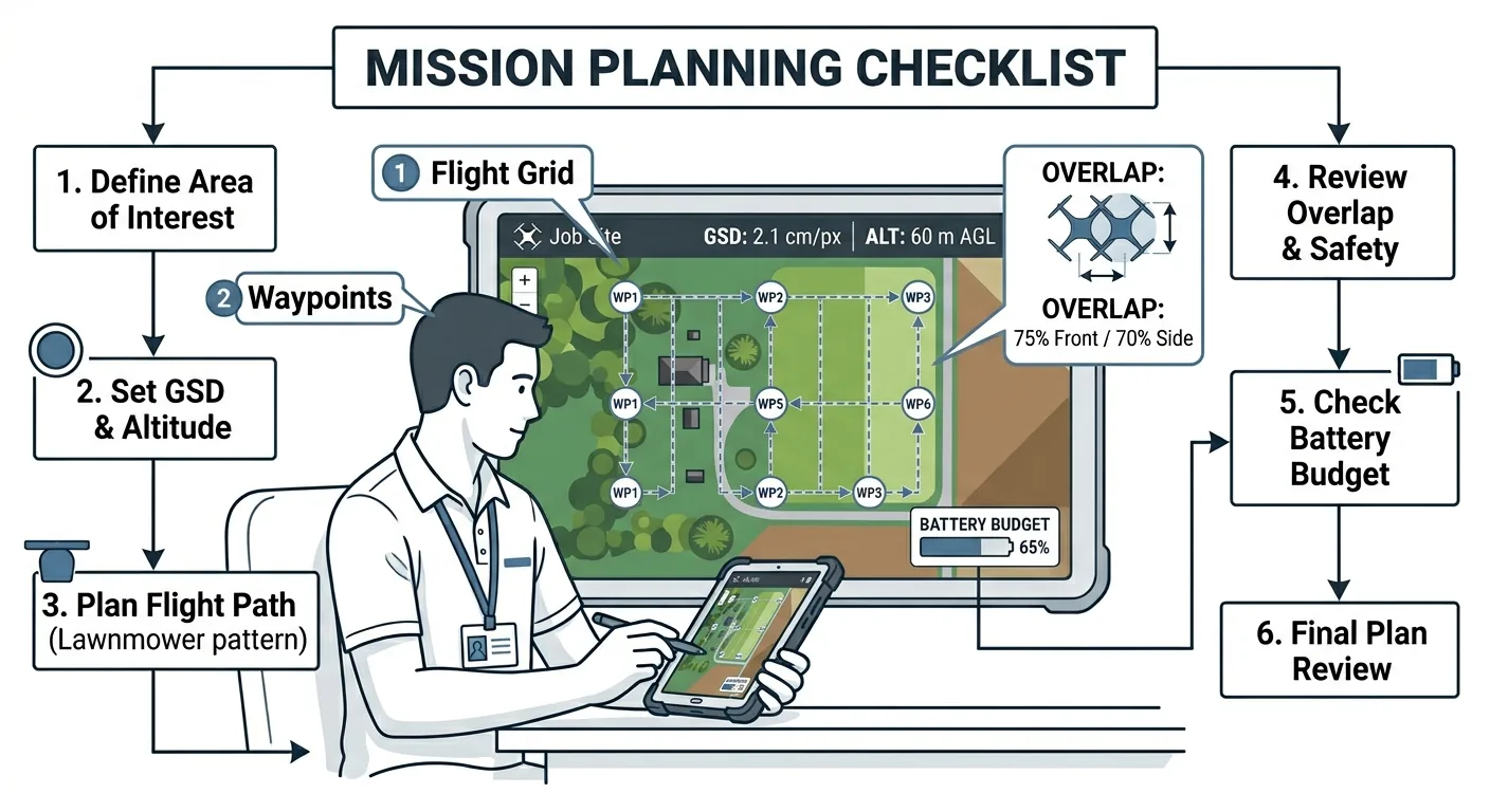
The Complete Mission Planning Checklist
Everything above, compressed into one table. Run through it before every mission. The planning math takes 15 minutes. The refly takes a full day.
| Phase | Item | ✓ |
|---|---|---|
| Accuracy & Specifications | Client accuracy requirement identified and documented (horizontal, vertical, GSD) | ☐ |
| Accuracy & Specifications | Project type matched to accuracy tier (see table above) | ☐ |
| Accuracy & Specifications | Required deliverables confirmed: ortho, DSM, contours, point cloud, 3D model | ☐ |
| Accuracy & Specifications | Contour interval or volume tolerance specified (if applicable) | ☐ |
| GSD & Altitude | GSD calculated for your specific platform and sensor using the formula | ☐ |
| GSD & Altitude | Flight altitude set to achieve required GSD — not higher, not lower | ☐ |
| GSD & Altitude | Terrain relief assessed: terrain-following enabled or multi-segment plan created | ☐ |
| Overlap | Terrain type classified: structured, mixed, low-texture, steep, or corridor | ☐ |
| Overlap | Frontal and lateral overlap set for terrain type (not left at app default) | ☐ |
| Overlap | Slope adjustment applied: +5-10% overlap for terrain >30% grade | ☐ |
| Overlap | Crosshatch pattern planned if 3D model or dense point cloud required | ☐ |
| Battery & Coverage | Total acreage calculated and battery count determined (using realistic endurance) | ☐ |
| Battery & Coverage | Landing threshold set at 25% battery remaining | ☐ |
| Battery & Coverage | Wind forecast checked and endurance adjusted for headwind conditions | ☐ |
| Battery & Coverage | Battery swap points aligned to end of flight lines, not mid-line | ☐ |
| Battery & Coverage | One spare battery beyond calculated requirement packed | ☐ |
| Flight App | Altitude entered manually and verified against GSD calculation | ☐ |
| Flight App | Overlap settings entered manually and verified against terrain type | ☐ |
| Flight App | Camera settings configured: shutter speed, ISO ceiling, white balance fixed | ☐ |
| Flight App | Waypoint altitude reference confirmed: relative vs. MSL vs. terrain-following | ☐ |
| Flight App | Flight line direction set perpendicular to longest axis (cross-slope on terrain) | ☐ |
| Flight App | Mission plan reviewed on map: full coverage of survey area with adequate buffer | ☐ |
Download the Mission Planning Checklist PDF
Get the complete mission planning checklist as a printable PDF. Every parameter decision from accuracy class to flight line direction — on one page.
Download the Mission Planning Checklist →
This is part 2 of the 6-part Drone Mapping Checklist Series. Previous: Pre-Flight Checklist. Next: GCP Deployment Checklist — every step between the truck and the first flight.